OpenIMU SPI Messaging Framework
1. Introduction
OpenIMU supports a SPI interface for data communications as a one of the choices. To enforce SPI interface mode ‘Data Ready’ signal needs to be forced HIGH of left unconnected on system startup. OpenIMU SPI interface signals described here.
OpenIMU operates as a slave device.
The master device must be configured to communicate with the OpenIMU using the following settings:
- Data transferred in 16-bit word-length and MSB-first
- fCLK ≤ 2.0 MHz
- CPOL = 1 (clock polarity) and CPHA = 1 (clock phase)
2. OpenIMU SPI communication model
OpenIMU has 128 8-bit registers accessible via SPI interface for reading and writing. The usage of these registers is completely user-defined in time of FW development. Access to the few registers is implemented in the examples as a reference:
Table 1. SPI registers used in the examples
Register Number Access Type Function Notes 82,83,84,88,89 (0x52 0x53,0x54,0x58,0x59) r
- Unit serial
- number
BCD format 86, 87 (0x56, 0x57) r Product ID 3000 - OpenIMU300
3300 - OpenIMU330
116 (0x74) r/w
- Unit Orientation
- MSB
- 6
117 (0x75) r/w
- Unit Orientation
- LSB
- 6
56 (0x38) r/w LPF Filter Type For Accel
- 7
57 (0x39) r/w LPF Filter Type For Rate Sensors
- 7
62 (0x3E) r Sensors Data Request
- 4
3. OpenIMU SPI Register Read Methodology
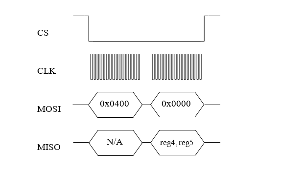
SPI master initiates a register read (for example register 0x04) by clocking in the address followed by 0x00, i.e. 0x0400, via MOSI. This combination is referred to as a read-command. It is followed by 16 zero-bits to complete the SPI data-transfer cycle. As the master transmits the read command over MOSI, the OpenIMU transmits information back over MISO.
In this transmission, the first data-word sent by the OpenIMU (as the read-command is sent) consists of 16-bits of non-applicable data. The subsequent 16-bit message contains information stored inside two consecutive registers (in this case registers 4 (MSB) and 5(LSB)).
Next figure illustrates register read over SPI interface:
4. OpenIMU SPI Block Mode Read Methodology
User can implement reading blocks of data with arbitrary length and information. Specific dedicated register address will indicate request specific block of data.
For example, register address 0x3e (62) indicates request for reading data block containing current data from unit sensors. Next table lists corresponding parameters:
Table 2. Block mode message format
Parameter Numer Size (bytes) Desctiption Status 2 Unit Status X_Rate 2 Rate Sensor output (X) (200LSB/deg/s) Y_Rate 2 Rate Sensor output (Y) (200LSB/deg/s) Z_Rate 2 Rate Sensor output (Z) (200LSB/deg/s) X_Accel 2 Accel Sensor output(X) (4000LSB/G) Y_Accel 2 Accel Sensor output(Y) (4000LSB/G) Z_Accel 2 Accel Sensor output(Z) (4000LSB/G)
Read of data block begins when the master requests a read from specific register address (i.e. 0x3E). Next figure illustrates the read sequence:
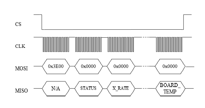
Note: Number of SPI clock pulses should be exactly equal to the length of predefined data packet (in this case – 144 (16 for address 128 for data)) otherwise interface may go out of sync.
5. OpenIMU SPI Register Write Methodology
The SPI master device can perform write into any register. The unit reaction on write operation is completely defined by the user. By default, corresponding data written without any reaction from unit. Written data can be read back. Unlike reads, writes are performed one byte at a time.
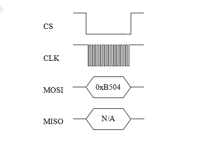
The following example highlights how write-commands are formed:
- Select the write address of the desired register, for example 0x35
- Change the most-significant bit of the register address to 1 (the write-bit), e.g. 0x35 becomes 0xB5
- Create the write command by appending the write-bit/address combination with the value to be written to the register (for example 0x04) - 0xB504
Next figure illustrates the register write over SPI:
6. OpenIMU Orientation programming
OpenIMU Orientation can be changed dynamically by writing corresponding values into the SPI registers 0x74 (MSB) and 0x75 (LSB). Data into register 0x74 should be written first. There are 24 possible orientation configurations (see below). Setting/Writing the field to anything else has no effect.
Table 3. OpenIMU Orientation field values
Registers 0x74/0x75 X Y Z 0x0000 +Ux +Uy +Uz 0x0009 -Ux -Uy +Uz 0x0023 -Uy +Ux +Uz 0x002A +Uy -Ux +Uz 0x0048 +Ux -Uy -Uz 0x0062 +Uy +Ux -Uz 0x006B -Uy -Ux -Uz 0x0085 -Uz +Uy +Ux 0x008C +Uz -Uy +Ux 0x0092 +Uy +Uz +Ux 0x009B -Uy -Uz +Ux 0x0041 -Ux +Uy -Uz 0x00C4 +Uz +Uy -Ux 0x00CD -Uz -Uy -Ux 0x00D3 -Uy +Uz -Ux 0x00DA +Uy -Uz -Ux 0x0111 -Ux +Uz +Uy 0x0118 +Ux -Uz +Uy 0x0124 +Uz +Ux +Uy 0x012D -Uz -Ux +Uy 0x0150 +Ux +Uz -Uy 0x0159 -Ux -Uz -Uy 0x0165 -Uz +Ux -Uy 0x016C +Uz -Ux -Uy
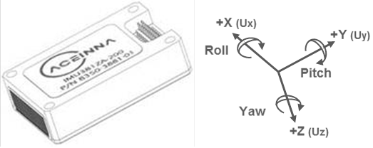
The default factory axis setting for the OpenIMU300ZI for SPI interface is (-Uy, -Ux, -Uz) which defines the connector pointing in the +Z direction and the +X direction going from the connector through the serial number label at the end of the unit. The user axis set (X, Y, Z) as defined by this field setting is depicted in figure below:
7. OpenIMU Digital Low Pass Filter selection
OpenIMU low pass filters can be changed dynamically for accelerometers and rate sensors writing corresponding values into the SPI registers 0x38 (for accelerometers) and 0x39 (for rate sensors). There are 7 possible low pass filter options (see below). Setting/Writing the field to anything else has no effect.
Table 4. OpenIMU Digital filter choices
Cutoff Frequency Filter Type 0x00 (0) N/A Unfiltered 0x30 (48) 50 Hz Butterworth 0x90 (144) 40 Hz Butterworth 0x80 (128) 25 Hz Butterworth 0x40 (64) 20 Hz Butterworth 0x50 (80) 10 Hz Butterworth 0x60 (96) 5 Hz (default) Butterworth